


Modbus is a popular industrial communication protocol in this article you Understand Modbus Protocol with Practical Example.
Introduction
You must have seen in war movies an Army General using morse code to communicate with the ground force.
Morse code used dots and dashes which were sent in patterns for the user to understand on the other end. Very cool indeed, right?
Yes, it was cool but it had its pros & cons. So, from time-to-time Humans have developed many methods for communication between 2 ends eliminating all the previously faced problems.
One of these communication protocols is Modbus. It was published in 1979 by Modicon (now Schneider Electric) for communication with PLCs in industrial devices.
How Modbus Work
Modbus is a two-wire protocol operated on low voltage, namely Rx and Tx. Sequences of 1s and 0s are transmitted for communication. The speed with which 0s and 1s are transmitted is called as Baud rate [Bits per second].
One device is the Master and the other device acts as slaves. Master initiates the query and the respective slave response.
Generally, Slaves are the devices that hold the data and Master is the device that wants the data. I will provide one example for your better understanding.
Examples of Modbus Protocol
Let’s say, you want power consumption data of a particular plant and choose an Energy meter that can support Modbus and write a program in PLC to fetch the data which can later be shown in SCADA.
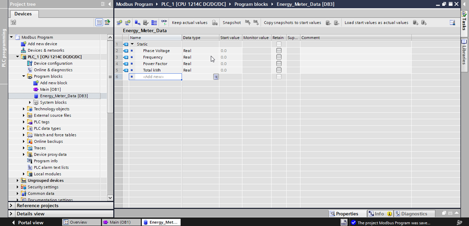
In the above case, the Energy meter acts as a slave as it already has preconfigured data such as Phase voltage, Frequency, Power factor, Total kWh, etc. and PLC acts as a Master which will initiate the query.
I will give another example for a better understanding. Let’s say you have a bunch of PLCs installed all over the plant and you want to see the process data in a centralized system DCS.
In this case, DCS acts as Master, and Field PLCs have to act as slaves. Because PLCs already have the data which is required in DCS.
Below are the non-volatile memory location standards on which any data can be placed.
| Type | Address | Function Code | Size | Access |
| Coil | 1-9999 | 1 | 1 bit | Read- Write |
| Discrete Input | 10001-19999 | 2 | 1 bit | Read-Only |
| Input register | 30001-39999 | 4 | 16 bits | Read-Only |
| Holding register | 40001-49999 | 3 | 16 bits | Read- Write |
Master and Slave Connection in Modbus
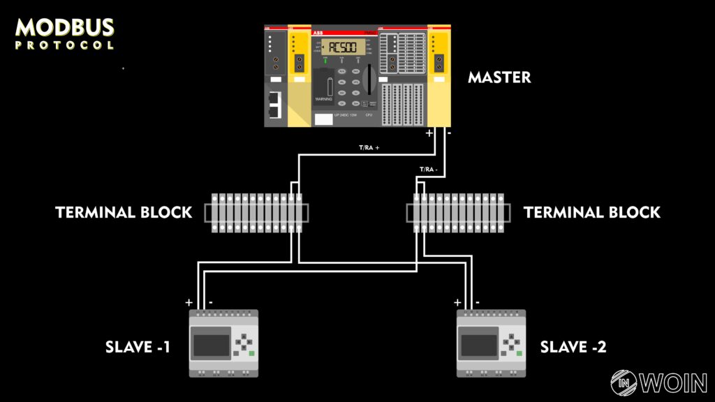
In the above electrical schematic diagram, loop all Positives and Negatives to the respective node on PLC together via a terminal block [A for +] & [B for -]. This way single slave can send queries to multiple slaves via 2 wires only.
Now you must be having doubt that the data between all the energy meter slaves mixed on the same bus then how to differentiate between this data is coming from this slave.
Hence the setting such as Slave Id has to be changed for each device connected on the same bus. A unique slave id will be assigned to each slave to distinguish between them
Here we have taken Slave id=1,2 & 3. Modbus will support up to 247 slaves from addresses 1 to 247 – address 0 is reserved for Master.
The number of slave addresses that can be used is determined by the communications link that is chosen. For example, RS485 is limited to a total of 31 slaves.
Other than slave id other parameters are also required to be configured in the slave [In our case Energy Meter] itself which are as below.
- Baud Rate = 9600
- Parity = None
- Data bits = 8
- Stop bit = 1
This setting is defined for the whole bus. Hence this setting has to be the same for all devices connected to the same Modbus Master, unlike slave id.
If you still have confusion between Master and slave as a thumb rule you can remember this way. Devices such as Energy Meter, Flow Meter, Variable frequency devices, etc. act as Slave.
How to Setup Modbus Protocol In PLC
In this section, you can get all the information on how Modbus will actually be set up in PLC. Commonly you can find Modbus Master and Slave Function blocks in any PLC programming Software.
For developing a program of anything in PLC. Keep in mind three basic steps.
A) Hardware
B) Software
C) Link used between the Hardware and Software.
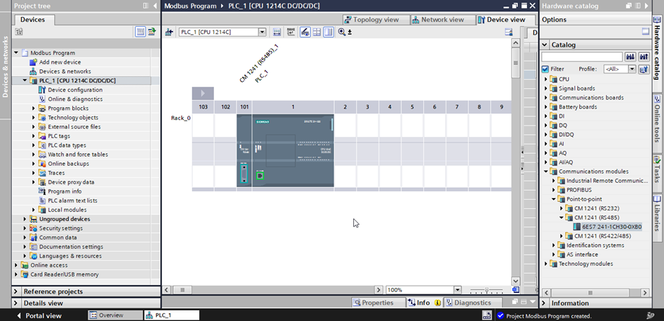
Steps to configure Siemens PLC for the Modbus program.
Hardware
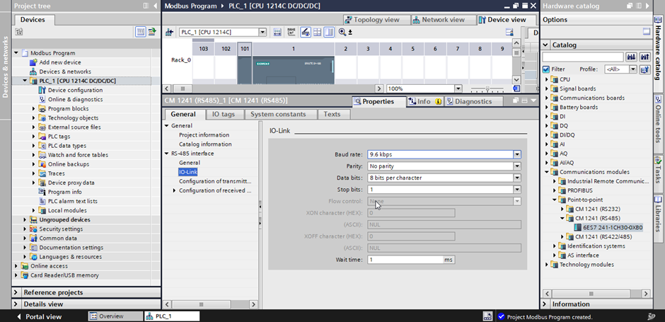
This is the hardware used for Modbus communication in Siemens PLC. We use CM 1241 as our Modbus card for this example.
Select your baud rate, parity, data bits, and stop bits. This information is provided by your Energy meter vendor.
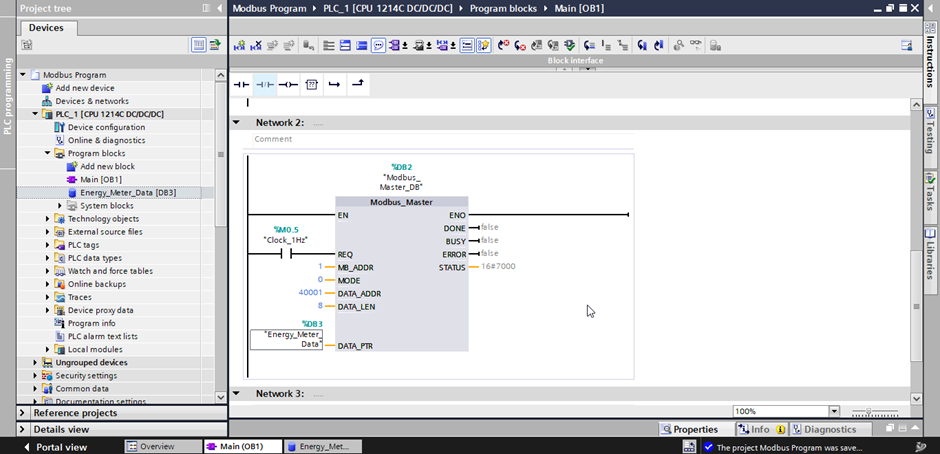
Software
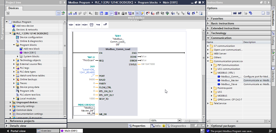
This is the ladder logic software code written in the PLC to fetch data.
This is the location in PLC where you will see the data after successfully configuring the PLC.
Link used between the Hardware and Software.
This is the hardware identification id [268] which will be used to link hardware and software.
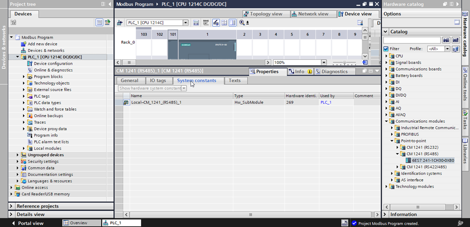
Modbus Comm load library is used in Siemens to connect the Hardware and Software using the above Hardware id [269]. Using this setting PLC will know that queries have to be transmitted on this port.
End Note
Even Though Modbus is one of the oldest communication protocols, it used still used even today at a large scale and for a true understanding of modern protocols.
fundamentals can only be cleared if you know this protocol very well. Good luck.
If you like this hope you also like our previous post What is the difference between PLC and DCS?