



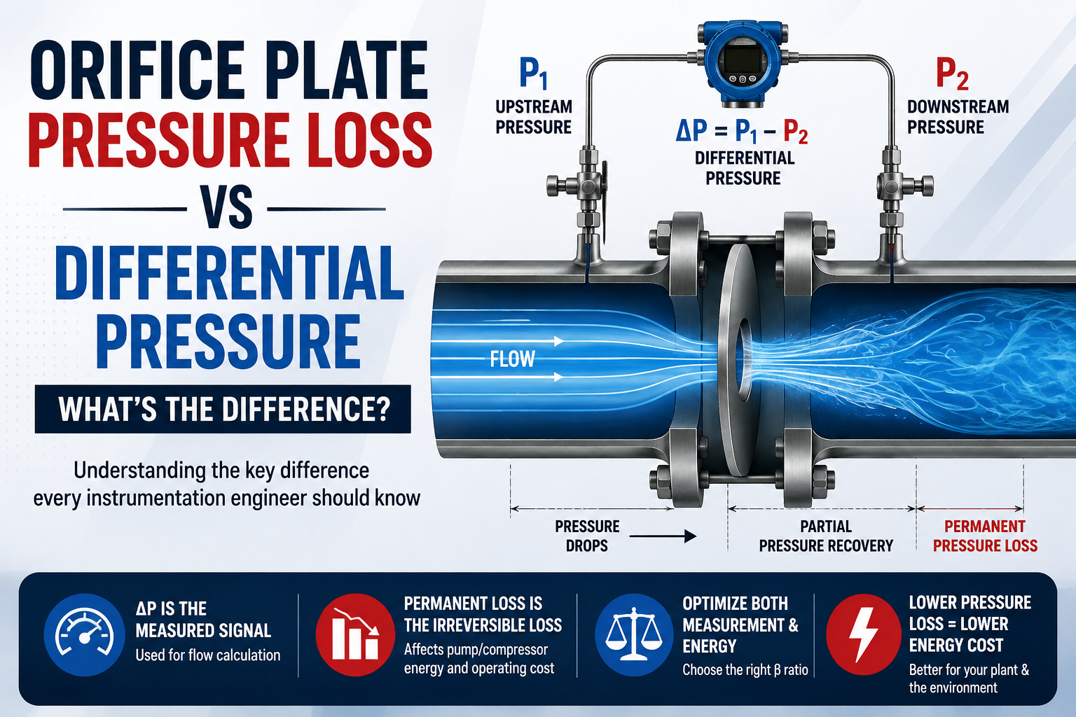
When working with an orifice flow meter, two pressure terms are used very frequently: Differential Pressure (ΔP) and Permanent Pressure Loss. They are related, but they are not the same thing.
Understanding this difference is important not only for flow-meter sizing, but also for evaluating the energy impact of an orifice meter on the process.
What is Differential Pressure (ΔP)?
An orifice plate creates a restriction in the pipeline. As the fluid passes through the restriction, its velocity increases and the static pressure decreases.
The pressure difference between the specified upstream and downstream pressure taps is called differential pressure.
In simple terms:
ΔP = P₁ − P₂

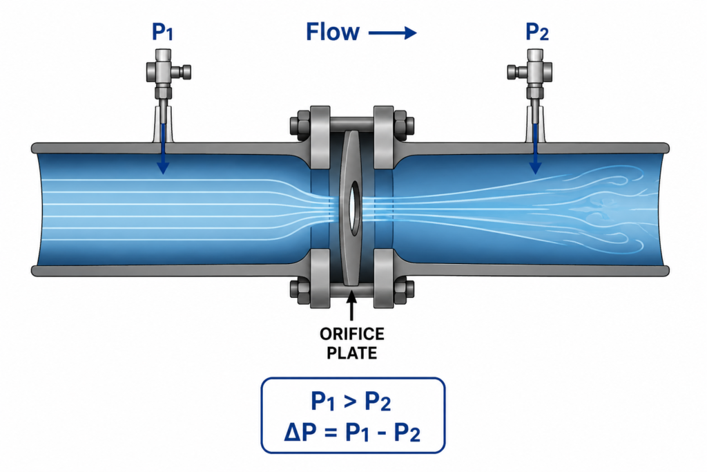
For a standard orifice meter, this differential pressure is the measurement signal used to calculate flow.API MPMS Chapter 14.3 / AGA Report No. 3 defines differential pressure as the static pressure difference measured between the upstream and downstream flange taps.
ISO 5167-2 similarly describes the measurement principle as the static pressure difference created between the upstream and downstream sides of the orifice plate.
What is Permanent Pressure Loss?
When the fluid passes through the orifice, the pressure does not simply fall and stay at the lower value.
Part of the pressure is recovered downstream as the high-velocity jet expands.
However, the recovery is not complete because of irreversible effects such as turbulence, flow separation and mixing.
The pressure that remains permanently lost is called permanent pressure loss.
So we can think of the process as:
Upstream pressure
       ↓
Orifice restriction
       ↓
Pressure drops
       ↓
Vena contracta
       ↓
Partial pressure recovery
       ↓
Permanent pressure loss
ISO 5167-2 specifically defines the permanent pressure loss, Δϖ, separately from the measured differential pressure, Δp. It relates the two using its pressure-loss equation in Clause 5.4.
Differential Pressure vs Permanent Pressure Loss
The easiest way to remember the difference is:
| Parameter | Meaning |
|---|---|
| Differential pressure (ΔP) | Pressure difference measured by the orifice pressure taps |
| Permanent pressure loss (Δϖ) | Pressure that is not recovered downstream |
| Purpose of ΔP | Flow measurement |
| Effect of permanent loss | Process pressure/energy loss |
Therefore:
ΔP is primarily the measurement signal, while permanent pressure loss represents an irreversible process loss.
They should not be treated as the same parameter.
How Does β Ratio Affect Pressure Loss?
The beta ratio is:
β = d / D
where:
- d = orifice bore diameter
- D = meter-tube internal diameter
The relationship is important because changing β changes the restriction created by the orifice.
Generally:
Lower β → smaller bore → stronger restriction → higher ΔP → higher permanent pressure loss
and:
Higher β → larger bore → lower restriction → lower ΔP → lower permanent pressure loss
The API/AGA reference data gives the following approximate relationship for a concentric, square-edged, flange-tapped orifice meter:
| β | Permanent Loss / ΔP |
| 0.20 | 96% |
| 0.30 | 91% |
| 0.40 | 84% |
| 0.50 | 75% |
| 0.60 | 64% |
| 0.70 | 51% |
| 0.75 | 44% |
For example, if:
β = 0.50
and:
ΔP = 400 mmWC
the reference relationship gives approximately:
Permanent pressure loss = 0.75 × 400
= 300 mmWC
The transmitter still measures 400 mmWC; approximately 300 mmWC represents the permanent loss according to this reference relationship.
Why Does Permanent Pressure Loss Matter?
This is where the topic becomes important from a process and energy perspective.
If a pump is pushing liquid through a pipeline containing an orifice meter, the pump must provide sufficient pressure to overcome the permanent pressure loss.
Therefore:
Permanent pressure loss → additional pump head → additional energy requirement
For a liquid, the hydraulic power associated with a permanent pressure loss can be estimated from:
Power = ΔP × Q
where:
- ΔP = permanent pressure loss
- Q = volumetric flow rate
For example, consider:
- Permanent pressure loss = 1 bar
- Flow = 500 m³/h
Flow in m³/s:
500 / 3600 = 0.1389 m³/s
Hydraulic power:
P = 100,000 × 0.1389
≈ 13.9 kW
So the orifice creates approximately 13.9 kW of hydraulic pressure-energy loss at this operating condition.
If the overall pump/driver efficiency is 70%, the corresponding upstream electrical requirement would be approximately:
13.9 / 0.70 ≈ 19.8 kW
This is why permanent pressure loss can become an important operating-cost consideration.
API/AGA explicitly states that permanent pressure drop is significant because energy has been lost in transporting the fluid through the pipeline.
Why Higher β Is Not Always Better
At first glance, the solution appears simple:
Increase β to reduce pressure loss.
But there is a trade-off.
Increasing β generally reduces the differential-pressure signal.
That means:
β ↑
 ↓
Restriction ↓
 ↓
ΔP ↓
 ↓
Permanent pressure loss ↓
 ↓
Energy loss ↓
But at the same time:
β ↑
 ↓
DP signal ↓
 ↓
Measurement margin ↓
This becomes particularly important at low flow.
API/AGA notes that when there is a wide swing from high to low flow, significant measurement errors can occur during low-flow operation if the same orifice plate remains installed. It states that operation between approximately 10% and 90% of calibrated differential span is generally considered good practice, while also noting that modern digital transmitters can increase rangeability.
Therefore, selecting the largest possible β is not necessarily the correct engineering solution.
What Should Be Checked During Orifice Sizing?
When sizing an orifice meter, engineers normally check:
- Minimum flow
- Normal flow
- Maximum flow
- β ratio
- Differential pressure
- Reynolds number
- Discharge coefficient
- DP transmitter range
- Measurement uncertainty
- Installation requirements
I would add one more important check:
Permanent pressure loss
A good orifice design should satisfy both:
Measurement requirement
and
Process pressure-loss requirement
For a complete assessment, the calculation should be performed across the operating range rather than only at one flow condition.
A Simple Engineering Approach
A practical workflow can be:
Flow Range
     ↓
Select β
     ↓
Calculate Orifice Bore
     ↓
Calculate ΔP
     ↓
Check DP Transmitter Range
     ↓
Calculate Permanent Pressure Loss
     ↓
Calculate Energy Loss
     ↓
Calculate Annual Operating Cost
     ↓
Check Standard / Process Constraints
If the permanent pressure loss is unnecessarily high, another β ratio can be evaluated.
This turns traditional orifice sizing into an energy optimization exercise.
Don’t Forget the Flow Conditioner
The energy assessment should not necessarily stop at the orifice plate.
If a flow conditioner is installed, it can introduce additional pressure loss.
For example, ISO 5167-2 gives pressure-loss coefficients for certain flow conditioners. The supplied standard gives approximately K = 2 for the Gallagher conditioner and approximately K = 3 for the Zanker conditioner.
Therefore, when comparing different meter arrangements, consider:
Orifice pressure loss + flow-conditioner pressure loss
rather than looking at the orifice alone.
Final Takeaway
The difference can be summarized in one sentence:
Differential pressure is the pressure signal used by the orifice flow meter, while permanent pressure loss is the portion of pressure that the process does not recover downstream.
For instrumentation engineers, ΔP is important because it determines the flow measurement.
For process and energy engineers, permanent pressure loss is important because it determines an ongoing energy penalty.
That is why a good orifice design should consider both.
The goal should not simply be:
“Get the required DP.”
It should be:
“Achieve the required measurement performance with the lowest practical permanent pressure loss.”
This becomes especially valuable in large, continuously operating pumping or compression systems, where even a relatively small pressure loss can translate into a significant annual energy cost.
References
ISO 5167-2:2003 — Measurement of fluid flow by means of pressure differential devices inserted in circular cross-section conduits running full — Part 2: Orifice plates.
API MPMS Chapter 14.3 / AGA Report No. 3, Part 2 — Orifice Metering, Specification and Installation Requirements.
WOIN — Orifice Flow Meter Sizing — used as the practical engineering style/reference for this article.
Related article: Orifice Flow Meter Sizing
Coming soon: Orifice Energy Loss Optimizer — Calculate permanent pressure loss, annual energy cost and potential β-ratio savings.
you like this article, and if you want to know about a functional safety certificate, check out my previous article.
And you can also follow our LinkedIn group which is specially made for sharing information related to Industrial Automation and Instrumentation.
