



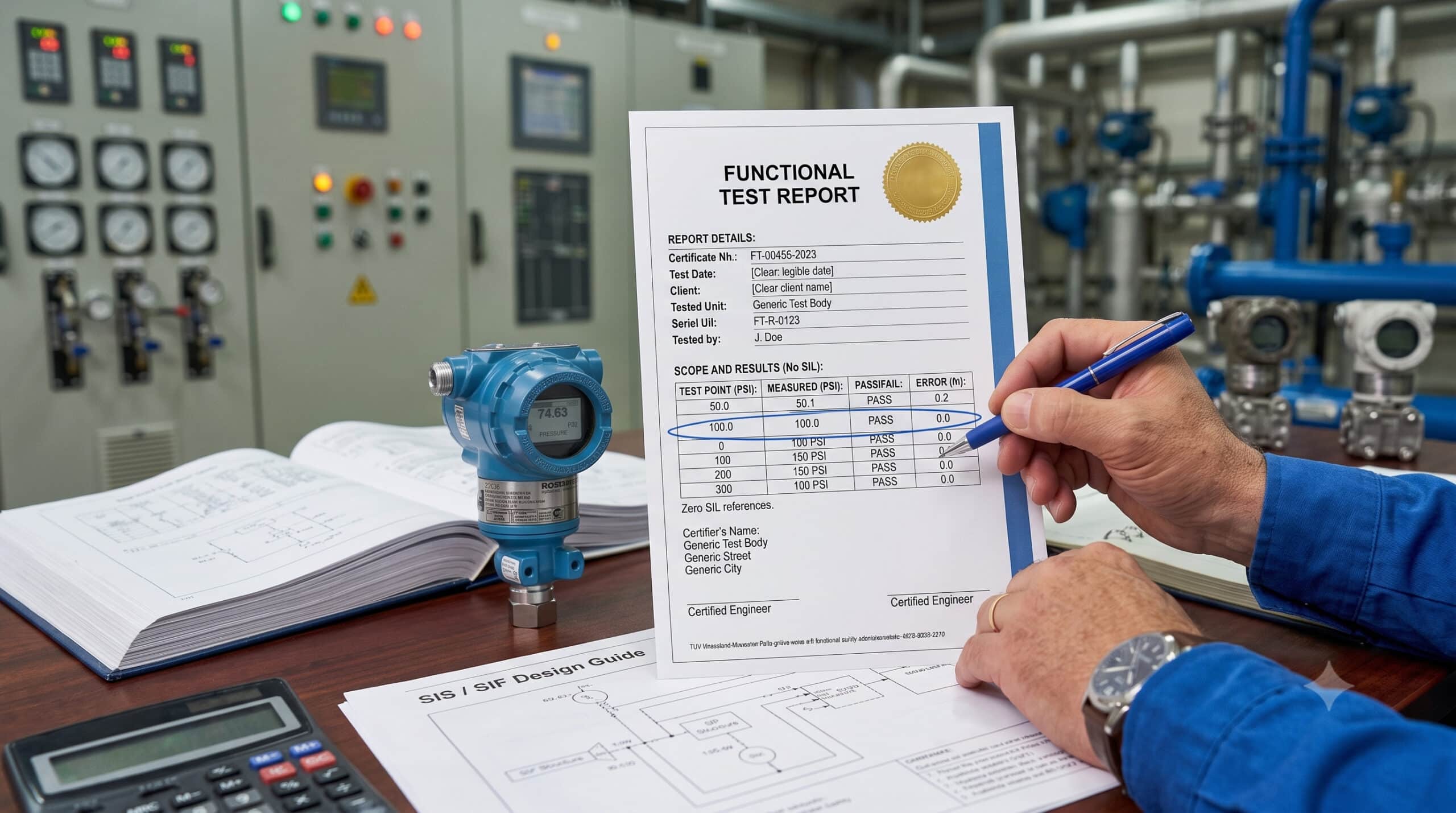
I used to think a functional safety certification was mostly a resume line — proof you sat through a course and passed a test. Then I actually looked into what these exams test, and separately, started paying real attention to what I could and couldn’t spot in a Functional Safety certificate myself. The gap between the two was bigger than I expected.
A certification doesn’t hand you new eyes. But the process of earning one — properly — rewires what you notice by default when you’re staring at a Safety Manual or a “Scope and Result” section. This is my attempt to explain what that depth actually looks like, and why it’s worth building even if you never sit the exam.
What the Certification Process Actually Tests
Two schemes dominate this space: CFSE/CFSP, administered by exida, and FS Engineer (TÜV Rheinland).
CFSE (Certified Functional Safety Expert) is the senior-level credential — it’s aimed at people who lead, coordinate, or review SIL selection and SIL verification work, and it expects around ten years of relevant experience (a bachelor’s degree in engineering lets you subtract a few years off that).
CFSP (Certified Functional Safety Professional) sits a level below, aimed at engineers executing safety lifecycle activities without necessarily leading them, and asks for roughly two years of experience.
The application itself requires a case study: a written account of a real project where you demonstrably carried out safety lifecycle work, cross-checked by independent referees who can vouch for your role. Only once that’s accepted do you sit the actual exam — a four-hour, open-book mix of short-answer and multiple-choice questions. You’re allowed to bring the standard itself into the room.
That last point matters more than it sounds. An open-book exam that’s still hard to pass isn’t testing recall — it’s testing whether you can navigate the standard fast enough, under time pressure, to apply the right clause to a scenario you’ve never seen before.
That’s a completely different skill from memorizing definitions. And the certificate isn’t a one-time badge either: CFSE/CFSP is valid for three years, and renewing it doesn’t require retaking the exam — but it does require showing you’re still actively working in the field, not just holding a certificate from a decade ago.
FS Engineer (TÜV Rheinland) works differently — it’s training-plus-exam rather than a pure competency review, typically requiring 3 to 5 years of prior experience and an engineering degree, with the certificate valid for five years before renewal. But the substance is the same: you’re tested across the lifecycle, not a single topic.
Note: neither scheme certifies you on “SIL” as an isolated concept. Both are structured around the full IEC 61511 safety lifecycle — hazard and risk assessment, SIL selection, Safety Requirements Specification, SIF design and verification, installation and validation, operations and maintenance, and proof testing. You can’t pass by knowing PFDavg formulas alone. You have to reason across the whole chain.
The Three Depths of Reading the Same Document
Here’s the part I think matters most for anyone not planning to sit a formal exam right now. The lifecycle knowledge these certifications test shows up as three distinct depths of reading the exact same Functional Safety certificate.
| Depth | What You See | What You Miss |
|---|---|---|
| Level 1 | “SIL 3 transmitter” — takes the datasheet label at face value | HFT, SFF, architecture constraints — the label alone means nothing |
| Level 2 | Checks HFT and SFF, understands the architectural constraints table | Whether the diagnostic assumptions behind λDU actually hold up in the field |
| Level 3 | Cross-checks λDU against how diagnostics are actually implemented downstream | Nothing meaningful — this is where audit findings get caught before they happen |
A rough framework, not an official taxonomy — but the pattern shows up consistently in real SIS audits.
I walked through a real example of Level 3 reading in a previous article on this site: a transmitter certificate stating HFT = 0 → SIL 2 and HFT = 1 → SIL 3, an SFF of 92.7%, and a Safety Manual line requiring output currents above 21.6 mA to be treated as a fault condition.
A Level 1 read stops at “SIL 3 capable.” A Level 2 read catches that single-channel use only supports SIL 2, because Type B devices with 90–99% SFF and HFT = 0 are capped there under IEC 61508’s architectural constraints table. A Level 3 read goes one step further: it asks whether the safety PLC’s analog input is actually configured to treat >21.6 mA as a diagnostic fault, or whether it’s silently clamping at 20 mA and throwing away the exact signal the FMEDA assumed would be detected.
That last check is the one that shows up as an audit finding two years into operation — not because the paperwork was wrong, but because nobody verified the field configuration matched the paper assumptions.
The same three depths show up outside certificates too. A LOPA report gets a Level 1 read as “the risk reduction number checks out” and a Level 3 read as “does the independent protection layer credited here actually meet the independence and integrity criteria the standard requires, or is it sharing a sensor with the SIF it’s supposed to be independent from?” A Safety Requirements Specification gets a Level 1 read as “the SIL target is stated” and a Level 3 read as “does this SRS actually specify response time, proof test requirements, and failure response behavior in enough detail that someone could verify the design against it later?” Once you’ve built the habit on one document type, it transfers.
Specific Details a Certified Engineer Learns to Check
Beyond HFT, SFF, and λDU, here’s what the lifecycle-wide scope of these certifications trains you to look for — things that don’t show up if you only study SIL tables in isolation:
- SIF boundary definition — where does the Safety Instrumented Function actually start and end? A certificate for one transmitter says nothing about the logic solver or final element’s contribution to the loop’s real PFDavg.
- Common cause failure (β-factor) in voting architectures — a 1oo2 architecture only gets you the reliability improvement the math implies if the two channels genuinely fail independently. Shared power supplies, shared impulse lines, or identical installation conditions erode that independence. Illustrative: IEC 61508-6’s checklist-based β-factor method typically lands somewhere in the 1–10% range for well-separated channels — meaning even a “redundant” pair still shares somewhere between 1% and 10% of its failure behavior. A design that ignores this and treats the two channels as fully independent is quietly overstating its own PFDavg improvement.
- Proof test coverage — a proof test that only exercises 60% of the failure modes a device can experience doesn’t give you the PFDavg improvement your calculation assumed. The certificate’s stated λDU assumes a specific proof test procedure, not “some” testing.
- Management of Change (MOC) trail — per IEC 61511, any change to a verified SIF — a setpoint, a proof test interval, a PLC configuration parameter — should go through MOC. A SIL verification package that was correct on day one can be quietly invalidated by an undocumented field change three years later.
- Bypass and override history — how often, and for how long, has this SIF actually been bypassed for maintenance? A SIF that’s frequently bypassed has a real-world risk reduction far lower than its paper PFDavg suggests.
- Systematic capability vs. hardware metrics — a device can have excellent λDU and SFF numbers on paper and still carry systematic failures from software bugs, specification errors, or design mistakes that no FMEDA captures. IEC 61508 tracks this separately, through development process rigor — a certificate’s hardware numbers don’t tell you anything about it.
- Diagnostic test interval vs. proof test interval — these are not the same thing, and mixing them up quietly breaks a PFDavg calculation. Diagnostic tests run continuously inside the device; proof tests are the periodic manual or automated tests that catch what internal diagnostics can’t.
Note: none of these show up on the device’s Functional Safety certificate. They live in the SIS design package, the proof test records, and the MOC log — which is exactly why lifecycle-wide competency matters more than device-level SIL trivia.
Why This Depth Is a Real Advantage
I’ve written before about the spec-stage-versus-audit-stage version of this argument, so I won’t repeat it at length here. The short version: catching an HFT/SFF mismatch, a proof test coverage gap, or a missing MOC record at spec review or FAT costs you an email and maybe a BOM change.
Catching the same gap during an operating-plant SIS audit costs a rework of the verification package, a documented finding, and someone’s afternoon spent explaining it to a client.
This depth also changes how you read vendor documentation before you’ve even bought anything. An RFQ response that quotes a bare SIL number without HFT, SFF, or a stated proof test regime isn’t necessarily wrong — but it’s incomplete in a way a Level 1 read won’t catch and a Level 3 read will flag before the PO is even issued.
The lifecycle-wide depth these certifications build — whether or not you ever take the exam — is what turns “checking the SIL label” into “checking whether the SIL claim actually survives contact with the real installation.” That’s a genuinely rare skill, and it’s the kind of thing that gets an engineer trusted with the SIS work nobody else on the team wants to touch.
How This Shows Up in an Interview or a Technical Review
It also shows up faster than people expect, in front of the people deciding who gets the next SIS assignment. A Level 1 answer to “walk me through this SIL verification” describes the PFDavg number and the SIL achieved. A Level 3 answer describes the SIF boundary, states which proof test interval the number assumes, flags where the β-factor came from, and notes what would break the calculation if the field configuration doesn’t match the paper.
Senior reviewers and interview panels don’t usually ask about λDU definitions — they ask things like “what’s the difference between your diagnostic test interval and your proof test interval,” or “what happens to this number if the proof test only covers 70% of failure modes instead of 100%.
” Those questions have no single correct number as an answer. They’re testing whether you actually reason through the lifecycle, or just recite the SIL that ended up on the datasheet. That distinction is very hard to fake, and it’s exactly what a real certification process spends years building.
EndNote
If you’re studying for CFSE, CFSP, or FS Engineer right now, I’d like to hear what part of the lifecycle scope surprised you most-it’s not the SIL math, it’s how much of the exam lives in places like proof testing and MOC that don’t get much attention in day-to-day project work.
Kindly share your experience if any i have prepared this article based on what i know and i also currently targeting to ger FS engineering certification.
you like this article, and if you want to know about thermowell design engineering. Procurement cycle for an instrumentation package Check out my previous article.
And you can also follow our LinkedIn group which is specially made for sharing information related to Industrial Automation and Instrumentation.
