



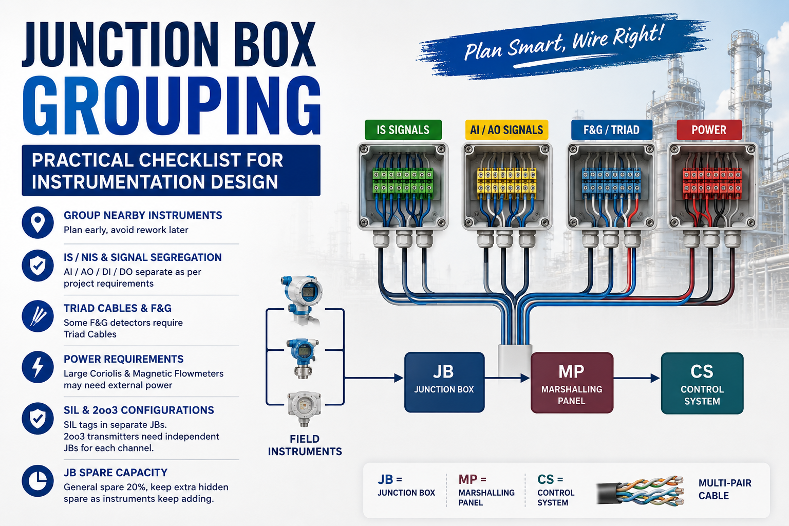
Junction Box (JB) grouping looks like a simple instrumentation design activity, but it can become a major source of rework during the later stages of an EPC project.
A poorly planned JB grouping philosophy can result in:
- Longer field cable routes
- Excessive cable tray loading
- Difficult termination and maintenance
- Incorrect segregation of signal types
- Additional JBs and marshalling hardware
- Problems with SIL independence
- Insufficient spare capacity
- Late-stage cable schedule and layout revisions

The basic principle is simple:
Group instruments logically, not merely geographically.
The uploaded JB Grouping Checklist highlights several important considerations that should be addressed before the JB layout, cable schedule and termination design become frozen.
This WOIN guide converts those points into a practical engineering approach that instrumentation designers can apply during project execution.
1. What Is JB Grouping?
A Junction Box provides an intermediate termination point between field instruments and the control-system/marshalling infrastructure.
A typical conventional signal path is:
Field Instrument → Junction Box → Multi-Pair Cable → Marshalling Panel → Control System
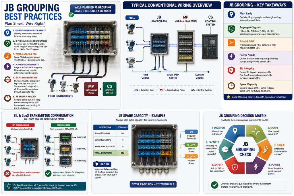
The diagram provided in the source document illustrates this conventional architecture and identifies:
- JB – Junction Box
- MP – Marshalling Panel
- CS – Control System
The diagram also shows multiple field instruments terminating into the JB before the signals are carried toward the marshalling/control-system side.
This means that the JB location and grouping philosophy directly influence the field cabling system.
2. Why JB Grouping Should Be Decided Early
One of the strongest recommendations in the source checklist is to identify instruments located near each other at an early stage.
The reason is practical: JB grouping becomes increasingly difficult to change once the project has progressed into detailed engineering, cable routing, procurement, installation and construction.
The checklist specifically warns not to underestimate this activity during the early project stages.
WOIN Engineering View
A good JB grouping study should therefore start while the following are still being developed:
Instrument Index → Plot Plan → Instrument Location → Cable Routing → JB Location → Cable Schedule
Instead of assigning JBs after cable routing, it is generally more effective to evaluate the field instruments and grouping requirements together.
3. Start With Instrument Location
The first step is to identify instruments that are physically located in the same or nearby process areas.
Typical grouping considerations include:
| Consideration | Engineering Objective |
|---|---|
| Instrument proximity | Reduce field cable length |
| Same process unit | Simplify field installation |
| Same plant area | Improve accessibility |
| Common routing direction | Reduce tray congestion |
| Similar termination requirements | Simplify JB design |
| Hazardous-area requirements | Maintain appropriate segregation |
The source checklist explicitly identifies nearby instrument locations as the first JB grouping consideration.
Important Point
Do not select the nearest possible location alone.
A JB that is physically close to an instrument may still be a poor choice if it creates:
- Improper signal mixing
- Excessive cable congestion
- Poor accessibility
- Inadequate segregation
- Future maintenance problems
Therefore:
Optimize JB location based on the complete instrumentation architecture, not distance alone.
4. Separate IS and NIS Signals
One of the key grouping considerations is segregation between Intrinsically Safe (IS) and Non-Intrinsically Safe (NIS) signals.
The checklist specifically calls for separate JBs based on IS/NIS signal requirements.
This is important because the segregation philosophy is not necessarily identical across all projects.
Project Design Basis Is Critical
Some clients may additionally require segregation based on signal type such as:
- AI – Analog Input
- AO – Analog Output
- DI – Digital Input
- DO – Digital Output
The source specifically notes that some major companies require separate JBs based on these signal categories and gives Saudi Aramco as an example, while emphasizing the need to follow the project design basis.
WOIN Design Rule
Never assume:
“All 4–20 mA signals can go into one common JB.”
The correct approach is:
Check Project Specification → Check Design Basis → Check Client Standards → Define JB Segregation Philosophy
5. Should AI, AO, DI and DO Have Separate JBs?
There is no universal answer that can be applied blindly to every project.
The source material explicitly indicates that certain clients may require separate grouping for:
AI / AO / DI / DO
Therefore, this decision must come from the applicable project requirements rather than from a generic JB philosophy.
A typical project grouping matrix may therefore look like:
| JB Category | Possible Signal Group |
| JB-AI | Analog Inputs |
| JB-AO | Analog Outputs |
| JB-DI | Digital Inputs |
| JB-DO | Digital Outputs |
| JB-IS | Intrinsically Safe |
| JB-NIS | Non-Intrinsically Safe |
| JB-SIL | Safety Instrumented Functions |
| JB-PWR | Instrument Power |
Note: This is an illustrative grouping framework. The actual arrangement must follow the project design basis and client requirements.
6. Triad Cable Signals Need Special Attention
The checklist also highlights triad cables as a possible reason for creating separate JBs.
This becomes particularly important for certain Fire & Gas (F&G) detectors, where triad cable construction may be used.
Why This Matters
If a project has a dedicated cable philosophy for particular F&G signals, mixing those signals into a general-purpose JB can complicate:
- Cable scheduling
- Terminal planning
- JB sizing
- Cable gland arrangements
- Segregation
- Construction activities
The source specifically warns that some F&G detectors use triad cables.
WOIN Recommendation
During JB grouping, create a cable-type review:
Instrument Type → Signal Type → Cable Type → JB Requirement
This prevents cable construction requirements from being discovered late in the design.
7. Do Not Forget Power JBs
Not every field device is treated as a simple signal-only load.
The checklist specifically identifies the need to check the requirement for Power JBs. It also warns that large-size Coriolis and magnetic flowmeters may require external power.
This is an easy issue to miss if JB grouping is performed only from the instrument signal list.
Therefore, review:
- Instrument power requirement
- Voltage level
- Current/load
- Signal type
- Cable type
- Power distribution philosophy
- Field termination requirements
Example
A flowmeter may appear in the instrument index simply as:
FIT-101 – Flow Transmitter
But from a JB design perspective, the designer must also understand whether the instrument requires:
Signal Only
or
Signal + External Power
That difference can influence JB architecture, cable arrangement and power distribution.
8. SIL Instruments Require Special JB Grouping
One of the most important points in the checklist is the segregation of SIL tags.
The source states that SIL tags should be grouped into separate JBs.
This is not simply a labeling preference.
Safety instrumented functions require appropriate independence in their signal paths, and the project architecture must preserve the required independence.
9. The 2oo3 Transmitter Example
The source gives a particularly important example involving a 2oo3 transmitter configuration.
For a 2oo3 arrangement, three transmitters participate in the voting architecture.
The checklist states that all three transmitters should be routed through separate JBs because the SIL loops require independent paths.
Conceptual Arrangement
Instead of:
TT-101 + TT-102 + TT-103 → Same JB
the grouping philosophy may require:
TT-101 → JB-SIL-01
TT-102 → JB-SIL-02
TT-103 → JB-SIL-03
The exact architecture must of course follow the approved SIS design and project requirements.
Why Is This Important?
Putting redundant safety channels through a common physical termination point can introduce a common-path consideration.
Therefore, redundancy should not be evaluated only at the logic solver level.
The instrumentation designer should consider independence throughout the signal path:
Field Instrument → Cable → JB → Marshalling → I/O → SIS
This is one of the most important engineering lessons from the checklist.
10. JB Spare Capacity — The Frequently Missed Item
JB capacity is another area where designers often focus only on the initial instrument list.
The checklist identifies 20% general spare capacity as a common starting point and additionally recommends considering hidden spare capacity because instruments can continue to be added during the later stages of a project.
Why Does This Matter?
Instrumentation scope evolves.
During EPC execution, you may encounter:
- New instruments
- Revised process requirements
- Additional alarms
- Additional F&G detectors
- Package equipment changes
- Client comments
- Control philosophy revisions
- Late vendor information
A JB that is exactly sized to the initial instrument count can therefore become a problem later.
Example
Suppose a JB initially has:
80 terminals required
with:
20% spare
Then:
Required capacity = 80 × 1.20 = 96 terminals
The source checklist additionally suggests maintaining another hidden margin during project development because the instrument count can continue increasing.
The exact spare philosophy should be established by the project specification.
11. JB Grouping Decision Matrix
A practical engineering review can use the following sequence.
| Question | Decision |
| Are instruments physically close? | Consider common JB |
| Are signals IS/NIS? | Verify required segregation |
| Does client require AI/AO/DI/DO segregation? | Create dedicated groups |
| Is triad cable involved? | Check separate JB requirement |
| Does instrument require external power? | Evaluate Power JB |
| Is instrument part of SIL function? | Apply SIL grouping philosophy |
| Is it a 2oo3 architecture? | Verify independent JB paths |
| Is sufficient spare capacity available? | Check project requirement |
| Can future instruments be added? | Maintain additional margin |
This matrix can be incorporated into the early instrumentation design review.
12. Recommended JB Grouping Workflow
A robust JB grouping workflow can be structured as follows:
Step 1 — Freeze the Instrument List
Start with the latest approved instrument index.
Step 2 — Identify Physical Location
Map each instrument against the plot plan and process area.
Step 3 — Identify Signal Classification
Classify each instrument as:
AI / AO / DI / DO / IS / NIS / SIL / Power / F&G
as applicable.
Step 4 — Review Cable Type
Identify:
- Pair
- Triad
- Multi-pair
- Power cable
- Other project-specific cable arrangements
Step 5 — Identify Special Requirements
Check for:
- SIL
- 2oo3
- External power
- F&G
- Client-specific segregation
Step 6 — Develop Preliminary JB Groups
Create logical JB clusters based on the above criteria.
Step 7 — Check Cable Routing
Verify that the proposed grouping does not create unnecessary cable lengths or poor routing.
Step 8 — Check JB Capacity
Apply the project’s spare philosophy.
Step 9 — Validate Against Design Basis
This is critical.
The uploaded checklist itself emphasizes reading and following the project design basis because client-specific requirements can change the grouping arrangement.
Step 10 — Freeze JB Schedule
Only after these checks should the JB schedule be considered sufficiently mature for downstream engineering.
13. Common JB Grouping Mistakes
Mistake 1 — Grouping Only by Geography
Two instruments may be physically close but still require separate JBs because of signal or safety requirements.
Mistake 2 — Ignoring Client Standards
A generic instrumentation philosophy may not satisfy a particular client.
The checklist specifically highlights client-driven AI/AO/DI/DO segregation as an example.
Mistake 3 — Missing Triad Cable Requirements
Certain F&G instruments may require triad cables and therefore a different grouping approach.
Mistake 4 — Ignoring External Power
Large flowmeters may require external power, which should be considered during JB planning.
Mistake 5 — Putting All SIL Signals Together
SIL grouping must consider the required independence of safety loops. The checklist specifically identifies separate JB treatment and the 2oo3 example.
Mistake 6 — Designing JB Capacity With No Future Margin
A JB that works on Day 1 can become undersized by the later engineering stages.
14. WOIN Practical JB Grouping Philosophy
A useful way to remember the entire process is:
LOCATION → SIGNAL → CABLE → POWER → SAFETY → CAPACITY
Before assigning an instrument to a JB, ask six questions:
1. LOCATION
Where is the instrument?
2. SIGNAL
What type of signal is it?
3. CABLE
What cable construction is required?
4. POWER
Does the device need external power?
5. SAFETY
Is it part of an IS, F&G or SIL application?
6. CAPACITY
Does the JB have sufficient spare capacity?
This simple framework can significantly improve the quality of an instrumentation JB grouping review.
15. Example of a Preliminary JB Grouping Structure
A project might develop a structure such as:
| JB No. | Primary Group | Typical Consideration |
| JB-101 | AI | Analog input signals |
| JB-102 | AO | Analog output signals |
| JB-103 | DI | Digital input signals |
| JB-104 | DO | Digital output signals |
| JB-105 | IS | Intrinsically safe signals |
| JB-106 | F&G | Fire & Gas / project-specific cable grouping |
| JB-107 | SIL-1 | Safety-related signals |
| JB-108 | SIL-2 | Independent safety path |
| JB-109 | POWER | Externally powered field devices |
Important: This table is an illustrative engineering example, not a universal standard. Actual grouping must be based on the approved project design basis, client specifications and SIS/F&G architecture.
16. JB Grouping and Cable Schedule Are Closely Connected
JB grouping should never be treated as an isolated document activity.
A change in JB grouping can propagate into:
Instrument Index → JB Schedule → Cable Schedule → Cable Routing → Tray Layout → Marshalling → I/O Allocation → Termination Drawings
Therefore, late JB changes can have a cascading effect across multiple engineering deliverables.
This is why early JB grouping is more than a drafting exercise — it is an interface-management activity between instrumentation design, electrical design, layout, construction and control-system engineering.
17. Final JB Grouping Checklist
Before finalizing a JB grouping philosophy, verify:
- Instruments in nearby locations have been identified.
- IS/NIS segregation requirements have been reviewed.
- AI/AO/DI/DO segregation has been checked against the client specification.
- Triad cable requirements have been identified.
- F&G detector requirements have been reviewed.
- Power JB requirements have been checked.
- Externally powered instruments have been identified.
- SIL instruments have been identified.
- 2oo3 configurations have been reviewed for independent paths.
- JB spare capacity has been checked.
- Future instrument additions have been considered.
- Cable routing has been reviewed.
- JB locations are accessible for operation and maintenance.
- Project design basis has been checked before finalizing the grouping.
Conclusion
JB grouping is a small-looking design activity with a surprisingly large impact on an instrumentation project.
The checklist reviewed for this article highlights the core principles:
Group nearby instruments intelligently.
Maintain required signal segregation.
Review triad and power requirements.
Treat SIL architecture carefully.
Provide adequate spare capacity.
And most importantly, follow the project design basis.
The conventional wiring illustration in the source also reinforces the fundamental architecture:
Field → JB → Multi-Pair → Marshalling Panel → Control System.
For an instrumentation designer, the objective is not simply to minimize the number of JBs.
The real objective is to achieve the best balance between:
Safety + Segregation + Cable Length + Maintainability + Capacity + Project Requirements
That is what makes a JB grouping philosophy robust for an EPC project.
you like this article, and if you want to know about a what is the difference between DP and PPL in orifice pls check my previous article
And you can also follow our LinkedIn group which is specially made for sharing information related to Industrial Automation and Instrumentation.
