Introduction
in this post, I will show you How the Transmitter generates 4-20mA signals and How the Two-Wire Transmitter works.
As you know in industry 4-20mA standard signal is used for transmitting analog value from transmitter to Analog card.
I am always curious to know how a 4-20mA signal is generated by the transmitter and what insight of the transmitter helps to generate the 4-20mA signal.
Today I will share with you how two-wire transmitters work and how they will generate standard analog signals that are connected to Analog input cards.
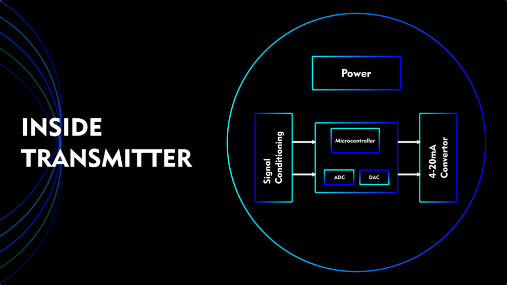
Before we start, we bypass the signal conditioning part because it will become too technical and complicated for one article. Sensor signal conditioning is very according to transmitter manufacturers.
in this post, I only show you that one’s sensor signal processing happened and now we have 1-5 volt to generate 4-20mA.

Nowadays all smart transmitters come with a built-in Microcontroller that handles smart functions and communication parts.
But in two-wire 4-20mA transmitter has a converter part that converts a 4-20mA current signal by getting 1-5V from the signal conditioning circuit of the sensor.
To understand this topic, I will create a Circuit simulation on Multisim to show how variable voltage with variable Constant current convention works.
How does a Transmitter generate 4-20mA Signal?
I am taking the 1-5V DC voltage source as a sensor signal that produces variable voltage by signal conditioning process.
As you can see from this circuit op-Amp works as a comparator that takes feedback voltage signal from sensing resistor R1.
R1 Resistor works as a feedback element and it is a standard 250 Ohm precision Resistor for 1-5v to 4-20mA convention.
After getting the voltage signal from the input side Op-Amp compares the input signal and feedback signal to generate output.
That becomes a setpoint of BJT that allows how much current will pass as per input gated from Op-Amp.
if not matching to the setpoint Op-Amp Puch the voltage to BJT to allow more current.
You can simulate this circuit by yourself and change parameters by using this live simulation circuit by MultisimLive. You can also access a free online Circuit simulator by clicking the button given below.
R3 Resistance of the transmission wire used to transmit data from the Transmitter to the Analog card. As you can see from the simulation, I changed the value of R3 resistors but it is not affected by the control signal.
And this is the true advantage of constant current circuits, it means control signal independent from loop resistance.
This is the one method for generating a constant current in the loop. However, there are multiple methods to make constant current circuits.
Working on a Two-Wire Transmitter
As you can see from the above circuit, I will explain how 4-20mA Constant current is generated by a constant current circuit that depends on the voltage applied to the Op-Amp.
Now we will see how two-wire transmitters work in the field and how it is wired in the field.

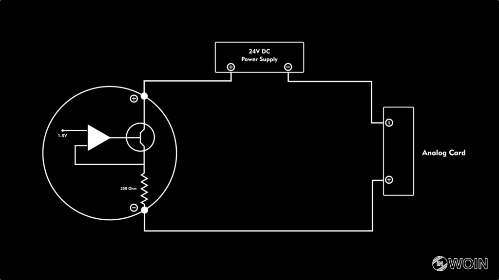
As you can see from the image two-wire transmitters connect the series with Power Supply and Analog Card.
The positive terminal of the 24V power supply is connected to the positive terminal of the transmitter.
The negative terminal of the transmitter is connected to the positive terminal of the Analog card input.
The negative terminal of the analog card is connected to the negative terminal of the power supply.
By connecting the Negative terminal of the power supply and Analog card we can introduce the same reference point for the analog card and power supply. It is very important for accurate measurement.
In the upcoming article, I will show you how an analog card works and what is inside of the analog card.
EndNote: –
This article is one step toward how the transmitter works. We get an overview of how 4-20mA converter circuits work.
if you have more information and want to share your knowledge on this topic. then I will provide a platform for you to share your knowledge and experience. Please contact us | at business@worldofinstrumentation.com


