


In this article i will cover how to do instrument cable sizing with a very basic and practical approach.
Introduction
In the world of industrial automation and process control, instrument cables are the nervous system, transmitting vital signals between field devices and control systems.
The reliability and accuracy of your instrumentation depend heavily on the proper functioning of these cables.
One of the most critical aspects of ensuring this reliability is correct instrument cable sizing. When it comes to instrument cable sizing calculation there is no clear articles are available on the internet.
Instrument Cable Sizing Calculation
Instrument cable sizing is primarily about ensuring the cable can safely carry the required current without excessive voltage drop, withstand potential short-circuit conditions, and maintain signal integrity. Main factor to be consider is voltage drop calculation.
Importance of Correct Sizing
- Signal Integrity: Undersized cables can introduce signal attenuation and noise, leading to inaccurate measurements.
- Voltage Drop: Excessive voltage drop can cause field devices (especially 24VDC transmitters or actuators) to malfunction or not receive sufficient power, impacting performance.
- Current Carrying Capacity (Ampacity): The cable must be able to safely carry the maximum operating current without overheating, which can degrade insulation and pose fire risks.
- Short-Circuit Withstand: In fault conditions, the cable must be able to withstand the surge current for a short duration without damage.
- Cost Efficiency: Oversizing cables can lead to unnecessary material costs and installation complexity.
- Compliance: Adherence to relevant electrical codes and standards (e.g., IEC, NEC) is mandatory for safety and regulatory compliance.
Key Factors Influencing Cable Sizing (Very Important Factors are mark with *)
- Type of Signal*: Analog Signals (4-20mA, 0-10V): Voltage drop is a critical concern, especially for long distances.Digital Signals (HART, Foundation Fieldbus, Profibus): While voltage drop is still important, impedance matching, shielding, and twisting become paramount for data integrity.Thermocouple/RTD Signals: Very low current, but specific conductor materials (e.g., extension wires for T/C) and shielding are crucial for accuracy and noise rejection.
- Current (Load)*: Determine the maximum operating current the cable will carry. For 4-20mA loops, this is typically very low (e.g., 20mA per loop), but multiple loops or higher power devices will have higher cumulative current.
- Voltage*: The nominal voltage of the circuit. (24 VDC Generally)
- Length of Cable Run*: Longer runs inherently lead to higher resistance and thus greater voltage drop.
- Permissible Voltage Drop*: This is often the limiting factor for instrument cables, typically 5% for control circuits, but can be much lower (e.g., 1-2%) for critical analog signals.
- Ambient Temperature: Higher temperatures reduce a cable’s current-carrying capacity. Derating factors apply.
- Cable Installation Method: How the cable is installed (e.g., in trays, conduits, direct burial, air) affects heat dissipation and current-carrying capacity. Derating factors apply for grouping.
- Conductor Material: Copper (Cu) is most common due to its excellent conductivity.
- Insulation Type: Determines the cable’s temperature rating and environmental suitability (e.g., PVC, XLPE).
- Shielding and Twisting: Essential for minimizing electromagnetic interference (EMI) and maintaining signal integrity, especially for low-level analog and digital signals. This doesn’t directly affect sizing for current/voltage drop but is vital for performance.
Calculation Steps
For instrument cables, the primary sizing criteria are usually voltage drop and current-carrying capacity (ampacity).
Short-circuit capacity is generally less of a concern for low-current instrument signals compared to power cables, but it’s good to be aware of. I am showing how to check cable voltage drop because it is important for Instrument cables.
Step 1: Determine Total Loop Current (I_total)
- For a single 4-20mA loop, I_total = 20 mA = 0.02 A.
- If multiple instruments share a common return or power supply and are bundled, sum their maximum currents.
- I_Total (mA) = Po_Load/Vo_Nominal (Po_Load (W) = Instrument total Power consumption and Vo_Nominal = Supply Voltage (24 VDC generally) or For 4-20mA signal we sonsider 20mA for Sizing
Step 2: Cable Voltage Drop Calculation
This is often the most critical factor for instrument cables.
The voltage drop (Vd) in a cable can be calculated using Ohm’s Law and cable resistance:
Vd = 2 × L_Total × I_total × R_cable
Vd = Voltage Drop
L_Total (Meter)= Distance between source and Load (Multibly by 2 consider because we will consider total round trip from Control Room to FIeld.)
I_Total (mA) = Total Loop Current
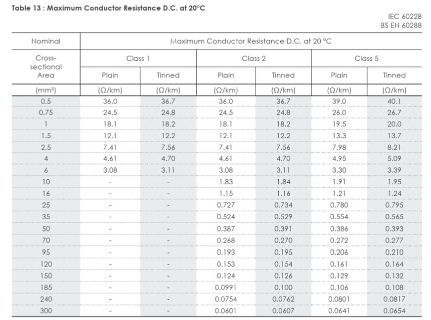
R_cable(Ohm/Meter) = You can find from Vendor cable catalog Class I cable are generally used in Oil and Gas Sector (Refer Below table and also cross check with your cable vendor technical data)
% Drop = Vd / V_Nominal <= 5
Practical Example of Instrument Cable Sizing
Let’s size a cable for a 4-20mA pressure transmitter:
Scenario:
- Instrument: Pressure Transmitter (4-20mA, 2-wire)
- Supply Voltage: 24 VDC
- Maximum Loop Current (I_total): 20 mA (0.02 A)
- Cable Length (L): 150 meters (one-way distance from DCS to transmitter).
- Permissible Voltage Drop (Vd_allowable): 5% of 24 VDC = 0.05 * 24V = 1.2 VDC
- Cable Type : 1.5 SQMM (Generally Used) based on the sizing result optimizion to be done by selecting lower cable cross section to reduce the cable cost.
- R_Cable = From above table need to convert from Ohm/Km to Ohm/Meter by Deviding 1000.
Solution:
1. Vd = 2 × L_Total × I_total × R_cable
2. Vd = 2 x 150 x 0.02 x 0.0121
3. Vd = 0.0726
Which is less than the our 1.2 VDC so Selected cable is correct in this you can also check for other lower corss section cable like 1.3 SQMM or 0.75 SQMM
EndNote
Proper instrument cable sizing is not merely a theoretical exercise; it’s a fundamental aspect of designing and maintaining reliable instrumentation and control systems.
By diligently considering current, voltage drop, environmental conditions, and installation methods, you can ensure that your signals are transmitted accurately and your field devices operate as intended.
Always refer to relevant international and local electrical codes, manufacturer’s data sheets, and industry best practices to make informed decisions. A little effort in sizing upfront can save significant troubleshooting and operational headaches down the line.
If you have any Suggestions pls let me know
If you like this article, and if you want to know How to Troubleshoot Pressure and Temperature Gauges. Check out my previous article.
And you can also follow our LinkedIn group which is specially made for sharing information related to Industrial Automation.