


Introduction
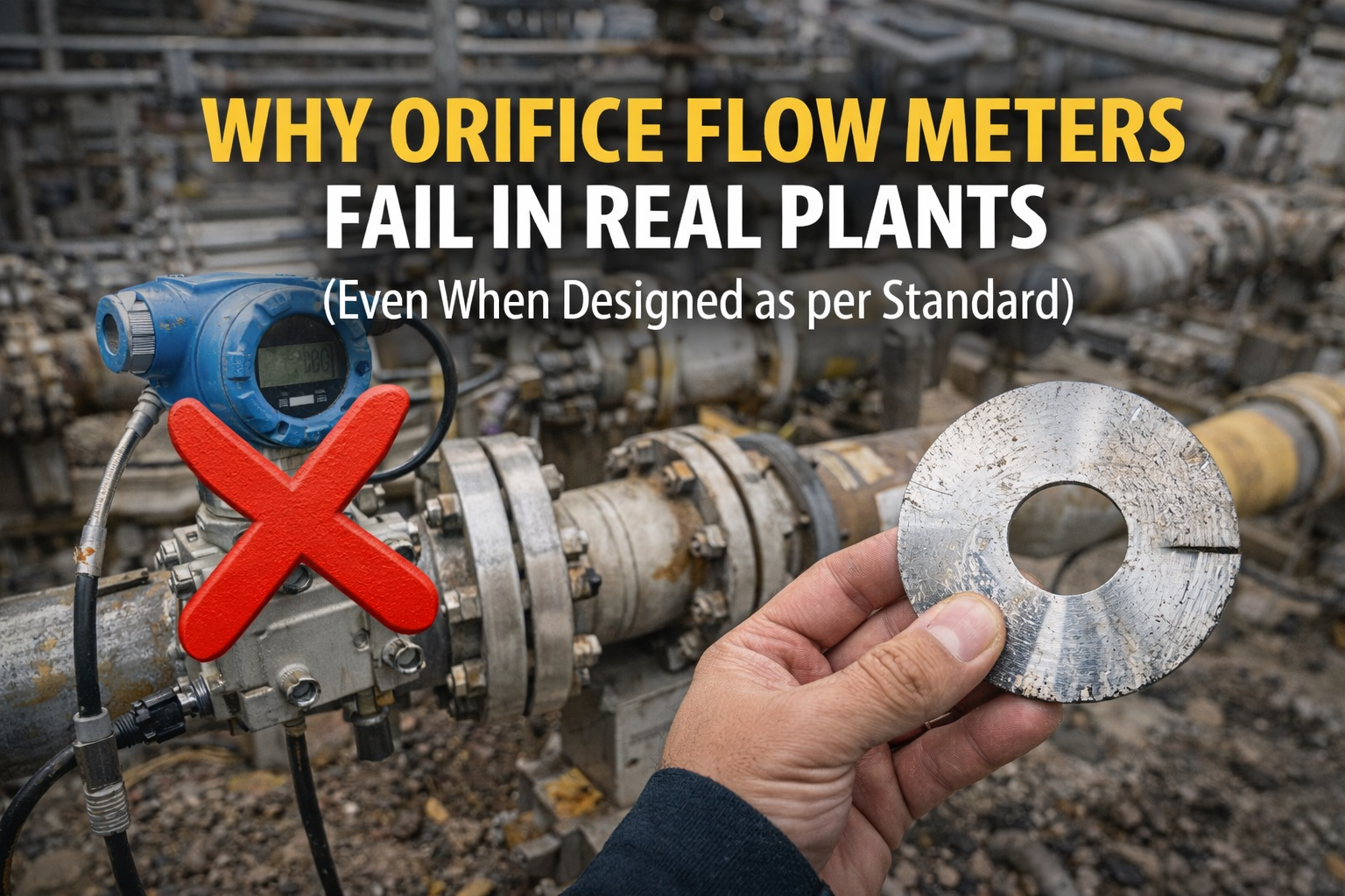
Orifice flow meters are among the most commonly used flow measurement devices in oil & gas and process industries.
They are simple, well-standardized, and widely accepted for both process and custody transfer applications.
Yet, in real plants, many orifice meters do not perform as expected, even when:
- Designed as per international standards
- Properly sized
- Installed with calibrated instruments
This article explains why orifice flow meters fail in actual plant conditions, focusing on practical reasons rather than equations.

How an Orifice Flow Meter Works (In Reality)
In theory, an orifice meter works by:
- Creating a restriction in the pipe
- Measuring differential pressure
- Calculating flow using standard equations
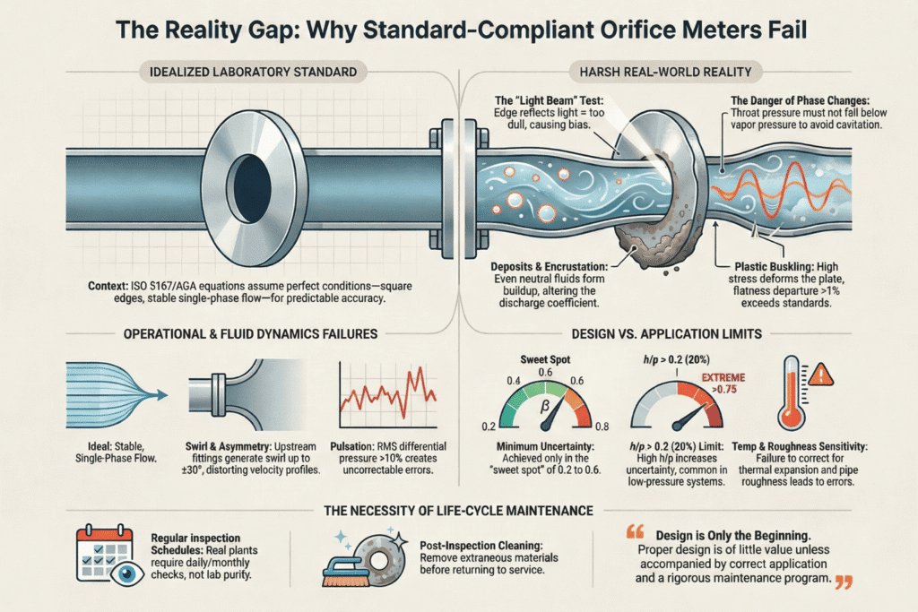
However, the equations assume ideal conditions, such as:
- Fully developed flow
- Correct straight pipe lengths
- Undisturbed velocity profile
In real plants, these assumptions are often not fully met, which leads to measurement errors.
Designed as per Standard ≠ Installed as per Standard
Most orifice meters are designed correctly on paper, but installation conditions differ:
- Limited plot space
- Existing piping constraints
- Late-stage layout changes
- Brownfield modifications
As a result, the final installation often deviates from standard requirements, even though the design calculations look perfect.
Insufficient Upstream Straight Length
One of the most common reasons for failure is insufficient upstream straight pipe length.
What happens in real plants:
- Elbows are installed too close to the orifice
- Multiple fittings exist upstream
- Straight length is reduced to “fit the layout”
Why this matters:
The orifice meter assumes a stable velocity profile.
Disturbed flow entering the orifice causes systematic flow error.
This error cannot be corrected by calibration.
Downstream Length Is Often Ignored
Downstream straight length is usually treated as “less important”.
In reality:
- Valves are installed immediately downstream
- Headers or branches exist close to the orifice
- Minimum downstream requirements are violated
While downstream effects are smaller than upstream, they still affect pressure recovery and uncertainty.
Flow Conditioners Are Misused
When straight length is not available, flow conditioners are often added.
Common issues:
- Non-qualified flow conditioners
- Incorrect orientation
- Wrong distance from the orifice
- No supporting documentation
A flow conditioner reduces sensitivity, but it does not make a bad installation perfect.
Multiple Upstream Disturbances Are Overlooked
Designers often consider only one upstream fitting.
In real installations, you may have:
- Elbow + reducer
- Valve + elbow
- Header + multiple bends
Standards require using worst-case disturbance logic, but this is frequently ignored.
The result is underestimated straight length requirements.
Orifice Plate Condition Is Taken Lightly
The orifice plate itself is often assumed to be “always correct”.
In practice:
- Plates are reused without inspection
- Edge damage goes unnoticed
- Orientation marks are ignored
- Plate certificates are missing
Even minor edge damage can cause a permanent flow bias.
Calibration Is Confused with Accuracy
A very common misconception:
“The DP transmitter is calibrated, so the flow is accurate.”
Calibration only verifies the instrument, not the flow measurement system.
Orifice meters are installation-dependent devices.
A calibrated transmitter cannot compensate for:
- Poor piping layout
- Distorted flow profile
- Incorrect straight length
Operating Conditions Change Over Time
Many orifice meters are designed for initial operating conditions.
Over time:
- Flow rate increases
- Gas composition changes
- Beta ratio becomes high
- Reynolds number shifts
The meter slowly operates outside its valid range, without triggering alarms.
Why Orifice Flow Meters Really Fail
Orifice meters fail not because standards are wrong, but because:
- Real plants evolve
- Installations change
- Assumptions are forgotten
- Compliance is assumed instead of verified
An orifice meter is only as accurate as its installation.
Conclusion
To ensure reliable orifice flow measurement:
- Verify straight lengths using actual piping
- Apply worst-case disturbance logic
- Treat flow conditioners carefully
- Inspect orifice plates regularly
- Separate calibration from compliance
- Revalidate meters when process conditions change
Understanding these practical aspects helps engineers prevent hidden measurement errors and avoid future disputes.
if you want to write an article on the website, please contact us by this mail id: contact@worldofinstrumentation.com
If you like this article, and if you want to know about hookup drawing. Check out my previous article.
And you can also follow our LinkedIn group which is specially made for sharing information related to Industrial Automation and Instrumentation.

