


Hello everyone. Today I am going to share knowledge on one important topic i.e. Bently Nevada System’s VMS system signal flow for vibration probes installed in the field.
VMS Systems are used for monitoring rotating machine health through Vibrations Vibration probes are the most important instrument to protect the machine from getting damaged.
Let us see how the field vibration probe is connected to the system and how we are able to see the value of the DCS.
In this article, we are going to discuss the Bently Nevada 3500 Vibration Monitoring System.
Elements in Bently Nevada VMS system (VMS)
The most common elements are used in the Bently Nevada Vibration Monitoring System. They are:
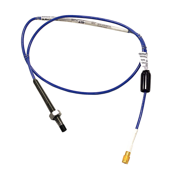
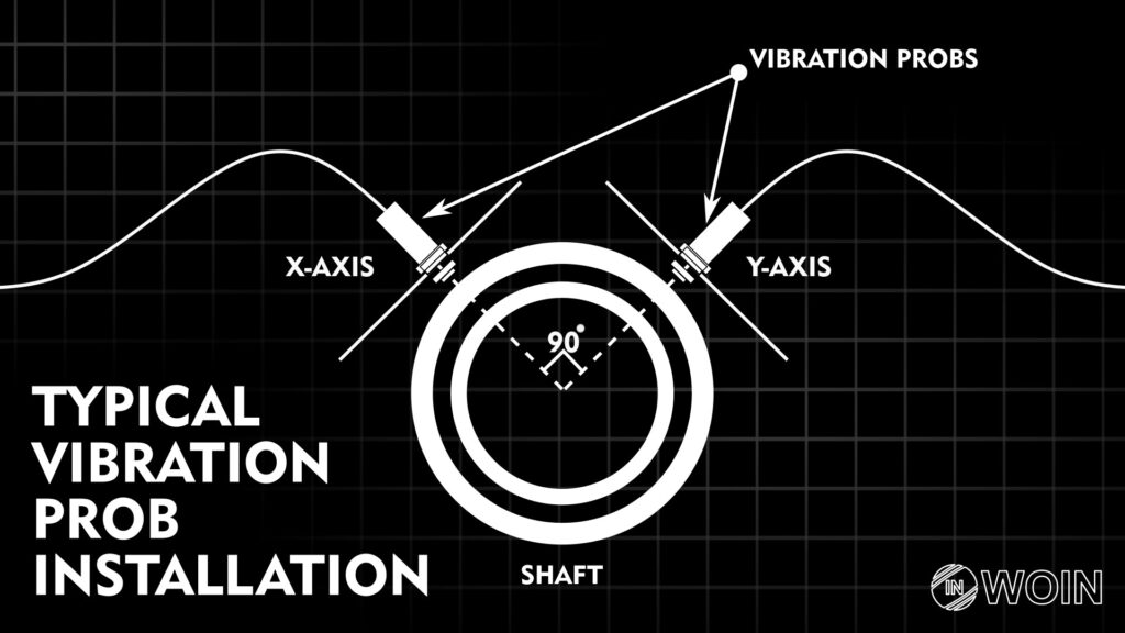
- Vibration probe: The vibration probe is installed on the machine in the field.

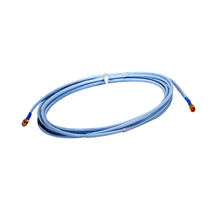
Extension Cable: The extension cable is used to connect the vibration probe to the further system
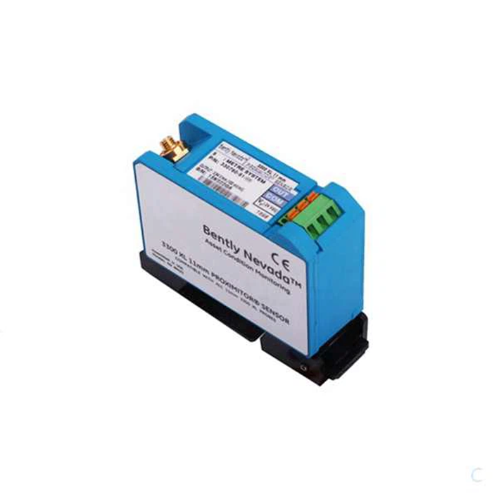
3. Proximitor: The Proximitor connects the vibration probe to the system. So we can say that Proximitor is a kind of barrier which connects the field device to the system.
The Proximitor is installed in the field itself inside a junction box. The vibration probe is connected to the Proximitor through an extension cable.
As we discussed, the vibration probe is connected to the proximitor through an extension cable.
The vibration probe is connected to the extension cable using a click lock type connector which is seen in the image in golden colour.
Then the other side of the extension cable is connected to the proximitor using a similar golden connector.
The proximitor is connected to the 3500 MCMS (Machine Condition Monitoring System) which we also call a VMS system.
This is located in the rack in the system cabinet in the control room or instrument cabinet rooms.
There is a specific module in the 3500 MCMS which is used to connect with the system which is installed in the field for vibration monitoring.
The module is 3500/40M connects to the proximitor and gathers the vibration data.
(Extra knowledge: The proximitor through the vibration probe, measures the distance between the vibration probe tip and the surface.
This system basically works on eddy current. RF waves are generated by the vibration probe tip and whenever a conductive material comes near the vibration probe’s tip, it changes the current due to the Eddy effect.
Now, let’s move to our main topic i.e. how is this system connected to other systems.)

Comparing this system to a normal PLC system, we can say that the vibration probe is an analog device like a pressure transmitter or other transmitter.
The extension cable is a special cable used in this vibration system; consider this cable like a simple cable that brings signal from the field to the marshaling cabinet in the PLC system.
Proximitor is like a barrier used in the PLC system. The 3500/40M module is like an analog input module (NOTE: Here 3500/40M is a special module for a vibration probe.
For temperature sensors, different module is available). There are different modules like the communication module, separate temperature input module, relay module, and communication module.
Now from here, 2 types of data are given to other systems. One is a hardwired signal and the other is through communication protocols like Ethernet TCP/IP and Serial communication (RS232, RS422, and RS485).
The relay module is 3500/32M. It has relays inside it which are used for hardwire signals for tripping machines through PLC/ESD/DCS.
The communication module sends data to the PLC/ESD/DCS through communication protocols like Ethernet TCP/IP and Serial communication (RS232, RS422, and RS485).
This was a 3500 rack and PLC/ESD/DCS systems communicate with each other.
EndNote
I hope these resources and Knowledge will become helpful to you in the future. You can also give your input through the comment section.
And I continue to make this type of resource and knowledge-sharing posts on my website.
if you want to write an article on the website, please contact us by this mail id: contact@worldofinstrumentation.com
If you like this article, you can also like my previous article on Temperature measurement without thermowell.
And you can also follow our LinkedIn group which is specially made for sharing information related to Industrial Automation and Instrumentation.


