


Introduction
If you work with orifice flow meters, you have definitely heard this:
“Ensure proper upstream and downstream straight length.”
But what does that really mean?
Why do we need it?
How much is enough?
And what actually happens if it’s not available?
This article explains upstream and downstream straight pipe length in simple words, without equations — just practical understanding.

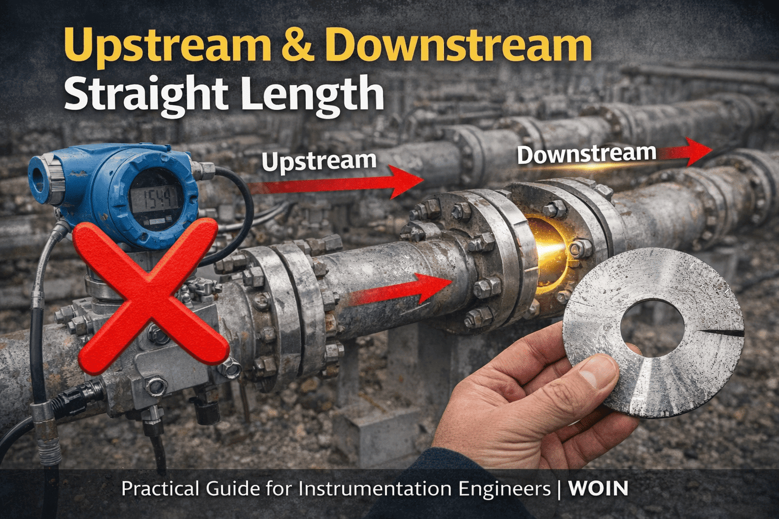
What Is Straight Length?
Straight length simply means:
A section of pipe with no fittings, no bends, no valves, and no disturbances.
It is the clean, undisturbed pipe section before and after the orifice plate.
Why is it required?
Because an orifice meter does not directly measure flow.
It measures how the flow behaves through a restriction.
And flow behavior depends heavily on what happens before it reaches the orifice.
Why Upstream Straight Length Is Critical
Let’s imagine water flowing in a perfectly straight pipe.
The velocity profile becomes smooth and stable.
Now imagine:
- An elbow just before the orifice
- Two elbows in different planes
- A partially open valve upstream
Suddenly the flow becomes:
- Swirling
- Uneven
- Distorted
The orifice plate assumes a fully developed, symmetrical flow profile.
If that assumption is wrong, the discharge coefficient used in calculations is no longer valid.
Distorted flow in = wrong flow out.
That is why upstream straight length is extremely important.
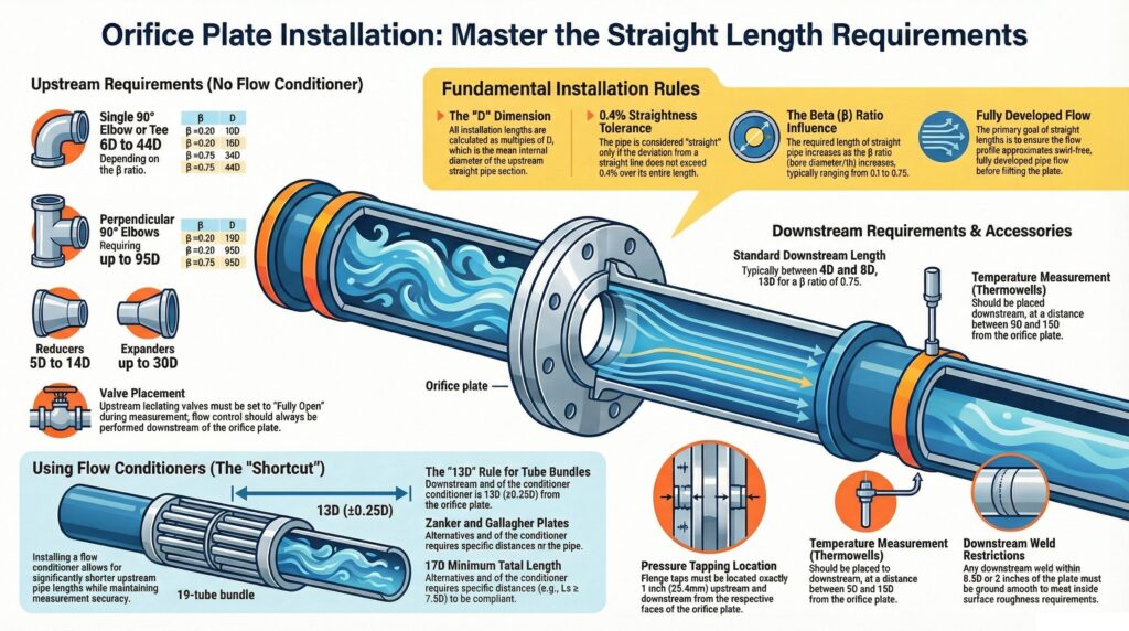
How Much Upstream Length Is Required?
The required length depends on what is upstream.
For example (typical industry guidance):
- Single 90° elbow → around 19D
- Two elbows in different planes → around 44D
- Control valve upstream → can go up to 80D
(D = pipe internal diameter)
The more severe the disturbance, the longer the straight length required.
In simple words:
The messier the piping upstream, the more straight pipe you need.
Why Downstream Straight Length Also Matters
Many engineers focus only on upstream piping.
But downstream piping also plays a role.
After the orifice plate:
- Pressure recovery happens
- Flow reorganizes
- Turbulence reduces
If a valve or fitting is installed immediately downstream:
- Pressure recovery can be affected
- Measurement uncertainty increases
- Stability may be impacted
Downstream effects are generally smaller than upstream, but they still matter — especially in custody transfer applications.
Common Misunderstandings
1. “Downstream Doesn’t Matter Much”
It matters less than upstream, but not zero.
2. “Calibration Will Fix It”
Calibration checks the transmitter, not the flow profile.
3. “We Have Some Straight Pipe, That’s Enough”
Not necessarily.
It must meet minimum required D values, not visual judgment.
4. “Only the Nearest Fitting Matters”
Wrong.
If multiple fittings exist, worst-case logic must be applied.
What Happens If Straight Length Is Not Available?
When straight length is insufficient:
- Flow profile remains distorted
- Differential pressure does not represent ideal conditions
- Calculated flow becomes biased
- Uncertainty increases
The meter may look stable.
The reading may look reasonable.
But it can still be wrong.
This is dangerous in:
- Custody transfer
- Energy accounting
- Performance testing
Because errors become financial issues.
Can Flow Conditioners Replace Straight Length?
Flow conditioners help by:
- Reducing swirl
- Improving flow symmetry
But they are not magic devices.
They must:
- Be qualified
- Be installed correctly
- Be positioned at proper distance
A flow conditioner reduces sensitivity, but it does not eliminate design responsibility.
Simple Field Example
Imagine a 300 mm pipe.
If upstream has two elbows in different planes, you may need around:
44 × 0.3 m = 13.2 meters of straight pipe.
In many plants, this space simply does not exist.
So what happens?
- Straight length is reduced
- Conditioner is added
- Assumptions are made
But unless verified properly, the installation may be outside standard limits.
Why This Matters More in Real Plants
In new projects:
- Layout may be compliant
But over time:
- Extra fittings are added
- Temporary piping becomes permanent
- Modifications are undocumented
The original straight length compliance slowly disappears.
That is why straight length must be verified during plant life, not only during design.
Final Summary
Upstream straight length ensures:
- Stable velocity profile
- Valid discharge coefficient
- Reliable flow calculation
Downstream straight length ensures:
- Proper pressure recovery
- Reduced uncertainty
- Measurement stability
In simple words:
Straight pipe gives the flow time to behave properly before and after the orifice.
Orifice meters are simple devices, but they are installation-sensitive instruments.
Understanding straight length properly prevents:
- Hidden measurement errors
- Disputes
- Uncertainty beyond standard limits
🔎 ISO & API Compliance Visualizer
Verify Your Installation Before It Becomes a Measurement Error
Most engineers assume straight length is compliant.
Very few actually verify it against:
- ISO minimum upstream/downstream requirements ISO_5167_2_2003_Orifice-plates
- API MPMS 14.3 installation clauses PART -1
- Multi-disturbance worst-case logic
- Beta-ratio impact
- Reynolds limits
- Flow conditioner validation
So I built something practical.
🛠 ISO & API Upstream / Downstream Length Visualizer for Orifice flow meter
I have developed a:
✔ ISO 5167 compliant straight length checker
✔ API MPMS 14.3 aligned disturbance evaluator
✔ Multi-disturbance worst-case selector
✔ Available-length vs required-length compliance checker
✔ Beta ratio & uncertainty warning engine
It visually shows:
- Required upstream length (in D)
- Required downstream length (in D)
- Effect of elbows / valves / reducers
- Additional uncertainty if non-compliant
- When flow conditioner becomes mandatory
👉 Check Your Installation Now
Click the button below to access the visualizer.
⚠ If you are using a mobile phone,
please switch to Desktop Mode for the best experience.
if you want to write an article on the website, please contact us by this mail id: contact@worldofinstrumentation.com
If you like this article, and if you want to know about hookup drawing. Check out my previous article.
And you can also follow our LinkedIn group which is specially made for sharing information related to Industrial Automation and Instrumentation.

