


Introduction
When an orifice flow meter is installed, we usually assume it is compliant because:
- The sizing calculation was done
- The flow computer is configured
- The DP transmitter is calibrated
However, both ISO 5167 and AGA-3 / API MPMS 14.3 make one thing very clear:
The validity of the flow equation depends on proper installation.
The discharge coefficient values provided in these standards are valid only if the geometry and installation conditions meet specified limits.
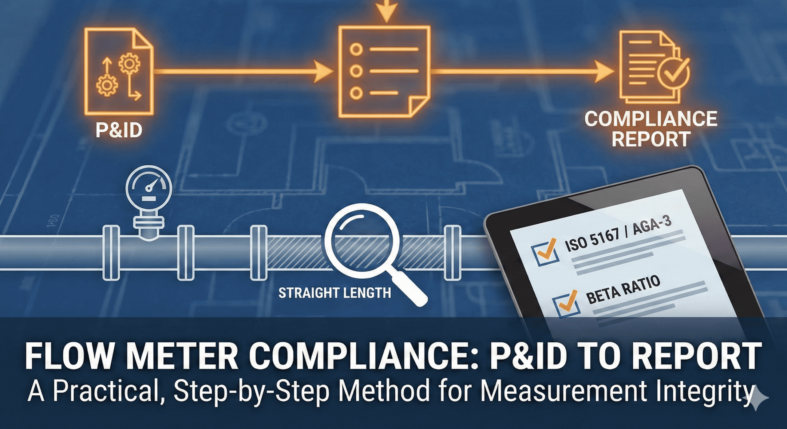
This article explains a practical, step-by-step method to verify compliance — starting from a P&ID and ending with a documented technical conclusion.
Flow Meter Verification Method Based on ISO 5167 & AGA-3
Step 1 – Confirm Which Standard Applies
Before checking anything, confirm:
- Is the meter declared as compliant with ISO 5167-2 (Orifice Plates)?
- Or with AGA-3 / API MPMS 14.3?
This matters because:
- Installation tables differ slightly
- Applicability limits differ
- Documentation expectations differ
You cannot mix:
- ISO installation rules with AGA computation logic
- AGA beta limits with ISO straight-length assumptions
Compliance must be evaluated against one declared standard.
Step 2 – Extract Installation Geometry from the P&ID
From the P&ID, identify:
- Pipe size (internal diameter reference)
- Type of primary element (concentric orifice plate)
- Pressure tap type (flange taps, corner taps, etc.)
- Upstream fittings
- Downstream fittings
- Reducers or expanders
- Control valves
- Branch connections
At this stage, do not assume compliance.
Just document the geometry.
Important:
P&ID shows design intent.
Field verification must later confirm as-built conditions.
Step 3 – Identify Upstream Disturbances
Both ISO 5167 and AGA-3 Part 2 specify minimum upstream straight lengths depending on disturbance type.
Common upstream disturbances include:
- Single elbow
- Two elbows in different planes
- Tee (flow through branch)
- Reducer
- Control valve
The standards provide minimum straight pipe requirements expressed in multiples of pipe diameter (D).
If multiple disturbances exist upstream, the worst-case requirement must be applied.
This is not an interpretation — it is inherent in how installation tables are structured.
Step 4 – Measure Available Straight Length
Now determine:
Distance from the last upstream disturbance to the upstream face of the orifice plate.
Then compare:
Required straight length (in D)
vs
Available straight length (in D or meters)
Repeat the same process downstream.
Key verification points:
- Is the pipe truly straight?
- Any unshown branch or tapping?
- Any thermowell intrusion?
- Any undocumented modification?
Compliance cannot be declared based only on design drawings if field conditions differ.
Step 5 – Verify Beta Ratio & Applicability Limits
Installation compliance alone is not sufficient.
Check:
- Beta ratio within allowable limits
- Reynolds number within applicability range
- Bore diameter within standard limits
- Plate geometry requirements satisfied
Both ISO 5167 and AGA-3 define beta ratio limits to ensure validity of the discharge coefficient correlations.
Operating outside these limits invalidates the standard uncertainty statement.
Step 6 – Confirm Pressure Tap Configuration
Standards specify:
- Tap location
- Tap diameter
- Tap type
- Tap spacing
For example, AGA-3 commonly assumes flange taps unless otherwise specified.
Incorrect tap geometry changes differential pressure measurement reference conditions.
This directly affects calculated flow.
Step 7 – Evaluate Flow Conditioner (If Installed)
If a flow conditioner is present:
Verify:
- It is recognized by the declared standard
- Installed at correct distance
- Installed with correct orientation
- Meets any qualification requirements
Flow conditioners allow reduction of required straight length only if installed per standard and manufacturer guidance.
They do not automatically guarantee compliance.
Step 8 – Document Findings Objectively
A compliance report should include:
- Declared governing standard
- Meter identification and service
- Pipe diameter and beta ratio
- Upstream disturbance summary
- Required straight length
- Available straight length
- Downstream evaluation
- Applicability verification (beta, Reynolds)
- Final compliance conclusion
Conclusion must be factual:
- “Compliant with ISO 5167 installation requirements.”
or - “Does not meet minimum upstream straight length requirement.”
Avoid emotional language or assumptions.
What Compliance Really Means
It is important to clarify:
Compliance does not mean perfect accuracy.
It means:
The installation satisfies the geometric and operating limits under which the standard discharge coefficient correlations are valid.
If installation violates those conditions:
- The meter may still operate
- The reading may appear stable
- But the published uncertainty limits no longer apply
This distinction is critical in custody transfer and audit scenarios.
Final Thought
Moving from P&ID to compliance report is not paperwork. A Practical Flow Meter Verification requierd
It is validation that:
- The installation matches standard assumptions
- The geometry supports the discharge coefficient correlation
- The measurement can be defended technically
Flow measurement accuracy begins with geometry, not electronics.
Calibration verifies the instrument.
Compliance verifies the installation.
Both are required.
if you want to write an article on the website, please contact us by this mail id: contact@worldofinstrumentation.com
If you like this article, and if you want to know about hookup drawing. Check out my previous article.
And you can also follow our LinkedIn group which is specially made for sharing information related to Industrial Automation and Instrumentation.

